A reader writes:
Thanks for your Embarrassingly Easy Case Mod page.
Sorry to be such a techno-dummy, but: You said that because each color-changing LED was 3V, you could connect 4 of them in series to a 12V source. So the LEDs divide the voltage between them? If that's true, how can you connect multiple AC devices to an exension cord and have each of them receive 117v?
Anyway, I'm converting an electronic theater organ to MIDI, and would like to add 20 color-changing LEDs to the console. (Thought you'd appreciate the details, eye-candy-wise.) How do you suggest I do that? If I wire them in series, what sort of DC power would I need?
I know you're a busy guy, so thanks very much for giving me a clue about this. I promise I'll do my best not to blow myself up.
Andy (Vancouver, BC)
Yes, you can run a string of four RGB LEDs from a 12V power supply. They're odd little critters, though, and it's important to understand why this works as well as just the fact that it does. You can make electronic things that work by just blundering around with no understanding of what's really going on, but it really does pay to spend some time learning the basics of at least DC electronics before you start on any electronic project. Hence, this lecture.
In the four-RGB-LEDs-from-12V situation, the LEDs can be regarded like ordinary passive DC-circuit components, like resistors or batteries. But LEDs can't usually be treated that way. Two-leg 5mm RGB LEDs may look like the usual kind of LED, but they're actually three LED dies with a tiny controller circuit, all in a normal 5mm LED package.
If you make a string of simple resistors that all have the same value - let's say, five two-ohm resistors - and hook one end up to the positive terminal of your DC power supply and the other to the negative, a current will flow that's determined by the total resistance and the voltage, according to Ohm's Law: Voltage in volts equals current in amps multiplied by resistance in ohms, or V=IR.
(Ohm's Law is usually written with "I" as the symbol for current, rather than A-for-amps, because when Georg Ohm came up with the Law nobody really knew what current was, and it was referred to as "Intensity". Feel free to write it with an A if you like.)
If the power supply is outputting, let's say, 12 volts, a string of five two-ohm resistors in series will work out as follows:
12 = I*2*5
12 = I*10
12/10 = I
I = 1.2
So the current in this circuit would be 1.2 amps. Because the resistors all have the same resistance, each one "drops" the same voltage. If you measure the voltage "across" the central resistive element of one of the five resistors in this circuit, it'll be 2.4 (12/5) volts. Measure across two resistors and you'll see 4.8V, three will be 7.2V, et cetera. (If the resistors in the chain have different values, they'll drop different amounts of voltage, and dissipate different amounts of power, making you use a polynomial equation if you want to figure out which resistor's doing what.)
To visualise this, think of the current as a flow of water in a hose and each resistor as a narrowing, or kink, in the hose. The higher the resistance, the narrower the path for water flow, and the more pressure (voltage) you'd need to achieve a given flow rate (current). (I've got water analogies for capacitors and inductors, too!)
To really get a grip on all this, I highly recommend that you get a little "breadboard" that you can plug components into without soldering (this sort of thing), and a selection of jumper wires (like this, or you can of course make your own), alligator-clip leads, resistors, capacitors, inductors, LEDs, battery holders etc to play with. And destroy - blowing up resistors, caps and LEDs can be very educational. Wear eye protection, especially when playing with electrolytic capacitors:
A proper adjustable bench power supply would also be nice, but would cost way more than all of the rest of this stuff put together. A lantern battery or hacked-up plugpack or PC power supply would be an adequate substitute, for this elementary stuff.
(You'll also need a multimeter, of course. A $10 cheapie like this will be fine.)
The gold standard for basic electronic education is a "science kit" sort of setup, like the classic Gakken My Kit 150 and Electric Block EX-150. But, again, they're a bit expensive.
OK, back to LEDs. Ordinary LEDs do not behave like simple DC components; they don't just have a "resistance" where hooking them up to a given voltage will cause a given amount of current to pass. A blue or white LED might be specified "3.6V, 20mA", but if you connect it directly to a 3.6-volt power supply, it'll get warmer and warmer and pass more and more current - "thermal runaway" - until, if the power supply's internal resistance is low enough, the LED burns up. This will happen for series strings of LEDs as well; if you make a string of ten "1.8V 20mA" red LEDs and connect it to an 18V power supply, it will probably not last long.
(Power supplies that have high internal resistance are a special case; you can connect LEDs directly across such a power supply and they'll work fine. This is why Photon lights and "LED throwies" work; they connect an LED directly across a lithium coin-cell watch battery, but the battery's internal resistance keeps the LED safe.)
The simple solution to this, as I explain in my old piece about building a caselight, is to put a resistor in series with your LED or LEDs. It's easy to figure out what resistor values to use for a single LED or even an array, but again, doing this without understanding what you're doing is not a great idea.
Series and parallel are bedrock concepts, here, with direct application to a number of everyday situations. Take your question about the powerboard that delivers full mains voltage - in your case 117V, a nominal 230V where I live - to everything plugged into it. It does that because the powerboard's outlets, like the wall outlets in your house, are all in parallel. (There are some tricky things about household power wiring in some countries, but they need not detain us now.)
Now, consider the old-fashioned kind of Christmas lights, with a long string of little bulbs that all go out if one bulb blows, so you have to replace every bulb in turn with a fresh bulb until you find the one that's actually died. That sort of behaviour is a dead giveaway that you're dealing with devices wired in series. In the Christmas-lights case, they're a string of low-voltage bulbs whose total voltage adds up to mains voltage, and they "share" the voltage between them just like a string of resistors. If mains is 240V, twenty 12V bulbs in series will run from it happily.
(Mains power is, of course, alternating current, not direct current. The two are very different, but incandescent light-bulbs don't care.)
OK, now let's finally get to your specific application, adding trippiness to an electronic organ. If the organ is at all modern, it'll run from low-voltage DC inside, and contain a power supply that converts the AC mains to whatever voltages it requires, just like a computer PSU. This doesn't mean it's safe to go fiddling around in there while the organ is turned on, but it does mean that there's probably some supply rail you could easily use to power plenty of LEDs, since they don't draw much power.
You will probably have to fiddle with the organ's guts while it's powered up to find a suitable power rail (unless you've got a schematic or service manual, or the innards of the organ are unusually well-labelled), so all usual safety disclaimers go here, along with my traditional link to the Sci.Electronics.Repair FAQ. But I wouldn't be surprised if you could easily find a 12V-ish rail across which you could connect a string of RGB LEDs, or even multiple strings in parallel.
That last bit is a "series-parallel" array. If you've got 12V and want to run more than four 3V RGB LEDs, you make up multiple strings of four and connect them all in parallel. People often seem to find this concept a bit slippery, but it's another of the things that it's important to grasp if you're to know what you're doing.
Here's how I wired that LED caselight:
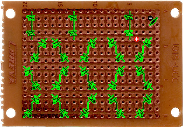
Those are 18 2-LED strings - and just one current-limiting resistor for the whole thing - all connected in parallel with each other. The little piece of "strip board" I used to make the caselight curls all of the copper traces around to make a rectangle and so is a bit confusing-looking, but electrically it's the same as two long wires, one positive and one negative, connected by 18 two-LED strings like the rungs of a ladder. (Rob Arnold's above-linked LED array wizard is very handy for figuring out LED array configurations, but remember that two-leg RGB LEDs aren't normal LEDs, so you really can just treat them as 3V DC components and not worry about resistors.)
If the organ doesn't turn out to have any tappable power rails, or if you just don't want to fool with them, the LEDs could less elegantly be run from a separate power supply, like a 12V DC plugpack. There's unexpected complexity waiting to ambush you here as well, though; if this page hasn't already turned you off electronics for life, try my essay on Humankind's Endless Quest for a Substitute Plugpack!
2 May 2009 at 6:53 pm
V=I*R
2 May 2009 at 7:04 pm
Whoops. And my bold revision of Ohm's Law wasn't the only thing that was screwed up in v1.0 of this post.
See what happens when I say "Eh, I don't need to proof it - I'll just click Publish and have dinner"?
2 May 2009 at 10:13 pm
Wait a sec. You don't need resistors on 2-legged RGB LEDs? Damn, and to think I made an extra trip across town to buy more resistors when I was making all the lounge room mood lighting with 10mm 3V RGB LEDs.
Could have saved myself some traffic!
3 May 2009 at 12:27 am
I haven't really thoroughly tested the two-wire RGB LEDs, but they - or, at least, the ones I bought - are definitely stable for as long as you like from 3V. Perhaps they actually do need current limiting if you run them hotter, but I doubt it.
(You'll still, of course, need resistors if you don't have enough LEDs per string to "use up" all of your power supply's voltage, or if its voltage isn't a clean multiple of three-point-not-much. Some eBay LED dealers also bundle resistors suitable for running one LED from 12V with all of their LEDs, including RGB ones.)
3 May 2009 at 2:08 am
Daniel,
E=IR
where E is Electromotive Force
3 May 2009 at 7:18 pm
I must try this resistor-free method! I still have half a dozen 3V RGB LEDs left over and my local St Vinnies is LOADED with old cordless phones and other appliances that don't work, but have 6/9/12v plugpacks.
Do you think unregulated has a significantly greater chance of failure than regulated?
3 May 2009 at 9:44 pm
On a related note, I'm a a sort-of noob when it comes to electronics (a little bit of knowledge and all that) and I'm looking for a circuit simulating program that's fairly straight forward to use - can anyone make any suggestions? The catch is that it has to have thermistors in the library of parts...
3 May 2009 at 10:19 pm
Don't use unregulated plugpacks for anything at all voltage-critical, unless you're loading them to at least a large portion of their maximum current rating.
As I mention in the plugpack post, an unloaded unregulated linear power supply will deliver root-two times its fully-loaded voltage rating. So a "12V" unregulated plugpack could deliver as much as 17V, giving four series-wired 3V devices an uncomfortable 4.25V to deal with. (Before I realised this, I blew up a battery charger.)
In reality, the-sticker-rating-times-root-2 won't necessarily actually quite line up with the unloaded voltage, and the full rated load may actually give you a bit less than the rated voltage, but you'll have to measure voltages to figure this out.
(Oh, and before you plug 21 strings of four RGB LEDs into a "300mA" plugpack because the LEDs only draw 14mA at 3V, bear in mind that it's possible that a wall-wart won't like it if you ask it to deliver its full rated current for an extended period. This reminds me of my original Amiga 500 "beige fanless brick" power supply, which I held up off the carpet with a couple of pickle jars, for better cooling.)
Modern lightweight switchmode plugpacks - which are now fairly common even in charity-store devices - should all be regulated, but I'd still poke a test lead into the barrel plug to make sure.
4 May 2009 at 8:00 am
So what's the inductor water analogy?
4 May 2009 at 9:27 am
The momentum of water flowing through a pipe should behave rather like an inductance, by default it'll keep flowing. If you suddenly close a valve (open a switch), the pressure (voltage) will temporarily spike. If it spikes high enough, it'll break the valve (arc over the switch) and keep flowing.
4 May 2009 at 9:34 am
Usually the inductor is regarded like a turbine or waterwheel that has inertia (inductance) and can't instantaneously change its rate of rotation (which is linked to the flow rate through it), and so it will create additional pressure (voltage) as required to resist changes in flow rate (current).
4 May 2009 at 12:09 pm
I'm sure you'll be gratified to know that the Firepower fiasco is on the SMH front page right now.
http://www.smh.com.au/opinion/truth-almost-as-sordid-as-the-lies-20090503-arep.html?page=-1
The words "trail of destructive bastardry" would be a good summation of the story...
4 May 2009 at 10:13 pm
While I'm not very good at electronic DIY, I do at least have a masters degree that mentions Electronics in the title... So I thought I'd do something cunning with a bunch of LEDs. Having read copiously on the subject I knew that the only problem is restricting the current through the diodes, and if you're using AC it can be done at zero nominal losses using a capacitor.
With 230VAC at 50Hz, I figured that 1uF should give a resulting current of 72mA, which ought to be OK for the LEDs I had bought. (They were rated at 150mA I believe.)
There are two advantages to this, First of all, the capacitor is fully reactive, so no energy is wasted, and secondly, you can plug in as many LEDs you want without changing the capacitor (within reason...)
In short, my schematics looked like this:
           | |

  ---------| |--------------------+

           | |                    |

                            +-----+-----+

                            |           |

                        +---+---+   ----+----

                         \     /       / \

                          \   /       /   \

                           \ /       /     \

                       -----+-----  +---+---+

                            |           |

                            +-----+-----+

                                  |

                            +-----+-----+

                            |           |

                        +---+---+   ----+----

                         \     /       / \

                          \   /       /   \

                           \ /       /     \

                       -----+-----  +---+---+

                            |           |

                            +-----+-----+

                                  |

 ---------------------------------+
Where more LED pairs can be added almost indefinitely.
I even ran this idea past a couple of 'real' electronics engineers in the office, and nobody could fault it. However, when I tried it, it didn't work...
I believe that the transients when switching it on and off contains too high frequencies, resulting in high peak currents through the LEDs, causing them to overheat.
Any ideas on how to fix it are very welcome...
4 May 2009 at 10:17 pm
Ooops, the
tag apparently doesn't retain whitespaces... Let's try a slightly different tack:
...........|.|-----------|.|--------------------+
...........|.|....................|
............................+-----+-----+
............................|...........|
........................+---+---+...----+----
.........................\...../......./.\
..........................\.../......./...\
...........................\./......./.....\
.......................-----+-----..+---+---+
............................|...........|
............................+-----+-----+
..................................|
............................+-----+-----+
............................|...........|
........................+---+---+...----+----
.........................\...../......./.\
..........................\.../......./...\
...........................\./......./.....\
.......................-----+-----..+---+---+
............................|...........|.........
............................+-----+-----+
..................................|
----------------------------------+
4 May 2009 at 10:20 pm
Hmmm, Slightly better, but backslashes are escaped. Let's try doubling them:
...........|.|

-----------|.|--------------------+

...........|.|....................|

............................+-----+-----+

............................|...........|

........................+---+---+...----+----

.........................\\...../......./.\\

..........................\\.../......./...\\

...........................\\./......./.....\\

.......................-----+-----..+---+---+

............................|...........|

............................+-----+-----+

..................................|

............................+-----+-----+

............................|...........|

........................+---+---+...----+----

.........................\\...../......./.\\

..........................\\.../......./...\\

...........................\\./......./.....\\

.......................-----+-----..+---+---+

............................|...........|.........

............................+-----+-----+

..................................|

----------------------------------+
4 May 2009 at 10:20 pm
That looks better. You know, a preview option would be very useful...
4 May 2009 at 11:26 pm
Popup, have you ever looked into Seoul Semiconductor's AC LED design? I think it uses two chains of series diodes; dunno about any capacitors. http://www.ledsmagazine.com/news/2/2/8
4 May 2009 at 11:56 pm
Yes, Malcolm, I have read about those. I think it's great (if not indispensable) if we want to be able to use LEDs for general lightning. But in this case I actually wanted to use some near-UV LEDs I already had, in order to illuminate a fish-tank.
5 May 2009 at 7:37 am
Ah, sorry, it sounded like you started with a blank sheet of paper.
BTW, I found this design which looks like yours, but still has a series 1K resistor in there. http://ourworld.compuserve.com/homepages/Bill_Bowden/lineled.gif
5 May 2009 at 2:02 pm
Just a little Public Service Announcement RE:Exploding Capacitors.
Newer models don't have this particular personality defect; but many older capacitors contain notrivial quantities of Polychlorinated biphenyls. Those are nasty little bastards on their own and their combustion/breakdown products are even worse. The ones that will give you a nice case of Yushchenko face have the highest media profile.
So, yeah. Newer ones should be less of an issue, probably not much more than a cough(assuming you wear eye protection); but don't go blowing up your big stash o' cheap surplus capacitors.
5 May 2009 at 4:17 pm
Going for something like this, Popup?
http://homepages.paradise.net.nz/bpresant/fish/sebaeuv.jpg
10 May 2009 at 10:22 am
Hi guys,
I'm the "Andy" whose questions inspired this very impressive page (with video, yet!).
Unfortunately, while all this info is fascinating, and of obvious value to those with the time and brainpower to absorb it, I find myself even more boggled. Yikes!
The organ in question has no power. I've removed all the original 30-year-old electronics, leaving only the manuals (keyboards), pedals, and switches, which I'll eventually interface with MIDI control. Whatever power I supply the LEDs will be from an AC-DC "wall wart".
At this point, the merciful thing to do might be to simply tell me:
_ How to connect the LEDs to each other and/or the PS.
_ What DC voltage/amperage the PS should be.
I think I could take it from there. Again, though, my utter admiration for the dissertation. Cheers, Andy
10 May 2009 at 2:43 pm
Quick and dirty: Get a modern lightweight regulated 12VDC plugpack with, say, a 500mA rating, and string RGB LEDs together into four-LED serial chains, and then connect multiple four-LED strings in parallel across the 12V, connecting the longer LED legs to the positive wire. 500mA should let you run 20 to 30 strings in parallel, if you want that many, without any trouble.
As I said, though, I really don't recommend you do this with no understanding of what you're doing. The world is well supplied with gimcrack electrical contraptions made by people who reckon "twist the wires together and add lots of electrical tape" is an adequate construction method, and some of those contraptions aren't even fire hazards. But you really, REALLY should, at the least, get a multimeter and some wire and components and a soldering iron, and fiddle around for a while, before blindly wiring stuff up and hoping for the best.
(And repairfaq.org is still great. :-)